Spray lubrication
Characteristics:
The characteristic of this system is, that the high tenacious lubricant is spread to active surface of teeth of the driving pinion by the air flow through the wide-beam nozzles with external production of lubricant-air mixture. Due to the pressure lubricant source for spray unit it is possible to divide the spray systems into three groups – spraying:
- With electric pump
- With barrel pneumatic pump SAF
- with EJECTORS
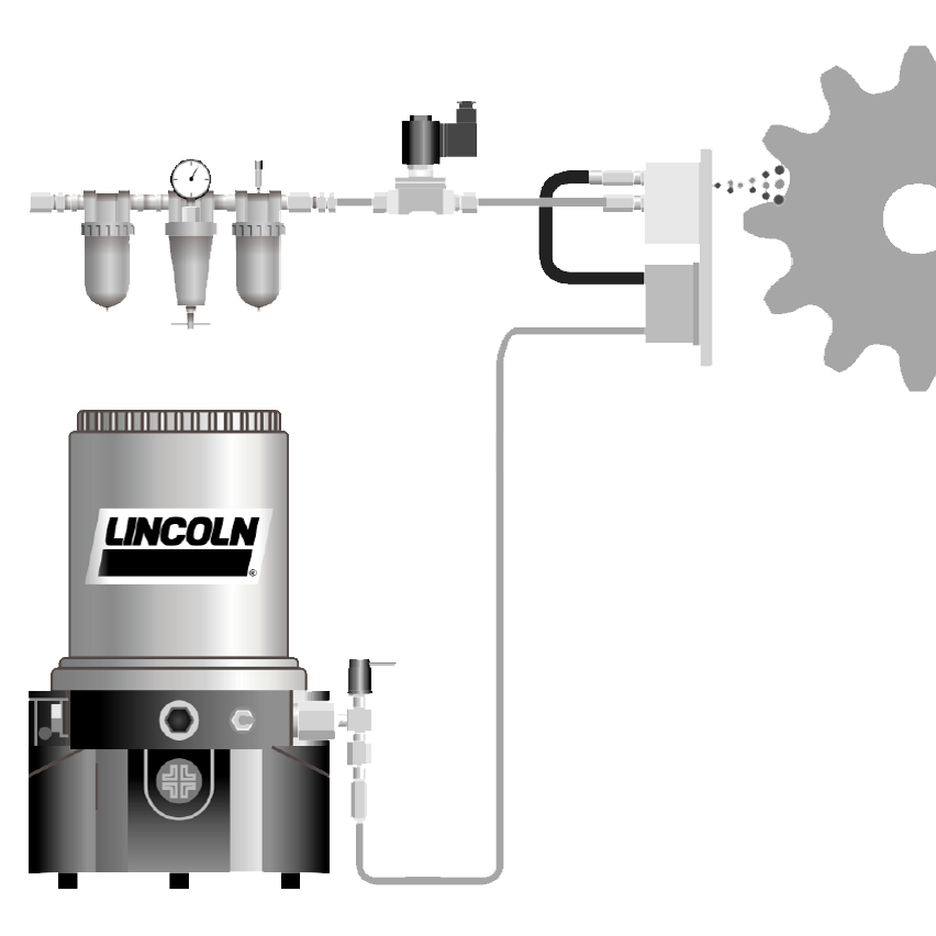
Spraying WITH electric pump:

Description:
The source of the lubricant is the multi-outlet electric piston pump (a). Spray unit (b) is supplied by the lubricant directly from the outlet of the pump element of the pump. If there are more spray units, each unit is connected to its own pump element. The spray unit consists of the progressive divider with the piston detector and of wide-beam nozzles SD. Number of wide-beam nozzles is dependent on the width of the gearing. The effective width of the spray pattern of one nozzle is 160 mm by optimal distance of nozzles from the impact point of lubricant on the sides of teeth. The system can be equipped by switching valves for switching of the spray units by two direction of rotation, eventually by lubrication of several pinions with different working regime. Air part is built by air unit (c) with closing valve, from which the air flows to the spray unit.

Function:
System works in cycles, that means that the working time (the pump runs) alternates the breaks (the pump stays still). When the pump (a) starts working, the pump element supplies the lubricant. At the same time, the valve 2/2 in the air unit (c) is open. The lubricant coming from the pump is by progressive divider, which is part of the spray unit, equally divided into all nozzles SD of the spray unit (b). The piston detector, by which is equipped the progressive divider, serves to control the lubrication function. The lubricant incoming to the nozzles SD is in the nozzle output mixed with the air – that means external mixture production – by which is the lubricant spread on the teeth sides. After the working time the pump is switched off and with a certain delay the valve 2/2 in the air unit is also switched off. So ends one cycle. The lubrication cycles are repeated during the whole operation period of the lubricated device. Alternatively it is possible to use so called controlled nozzles, which automatically control the air incoming so, that the air flows only as long as the lubricant flows to the nozzle. Usage of these nozzles rapidly lowers the air consumption.
Standard elements for spraying with electric pump:
a - Pumps
b – Spray units
- with progressive divider SSV-N (with function controlling), eventually SSV (without controlling function), 1-5 nozzles SD (uncontrolled), or SDL (controlled)
c – air units
- air unit 2/2-1/8"; air unit 2/2-1/4"; air unit
2/2-1/2" (dependent on the number of nozzles)
Additional parts of the system:
- Accessories – valves 3/2 for branches switching
- Lubricant distribution (tubes, hoses, screw-coupling, anchoring and assembly material)
Main fields of usage:
For gearing transmissions of smaller or middle dimensions with smaller or middle lubricant consumption, as crank presses, spindle presses, paddlewheels and rotation axis of big excavators, ball mills and rotation furnace in cement works and so on.
Spraying WITH pump SAF:

Description:
The source of the lubricant is the pneumatic barrel pump SAF (a) with one or two outlets, for connection of one or two spray units. Spray unit (b) consists of the progressive divider with piston detector and of wide-beam nozzles SD. Number of wide-beam nozzles is dependent on the width of the gearing. The effective width of the spray pattern of one nozzle is 160 mm by optimal distance of nozzles from the impact point of lubricant on the sides of teeth. The system can be equipped by switching valves for switching of the spray units by two direction of rotation, eventually by lubrication of two pinions with different working regime. The air part is built by air unit with closing valve (c) for spray unit and by air unit with the 3/2 valve for the pump SAF.  _x000D_
Function:
System works in cycles, that means that the working time (the pump runs) alternates the breaks (the pump stays still). During the working time the pump makes under the pressure ca 6 s the particular strokes and by each stroke it forces the unit volume of lubricant of 1,1 cm3. The valve 2/2 in the air unit (c) is open all that time. The lubricant coming from the pump is by progressive divider, which is part of the spray unit, equally divided into all nozzles SD of the spray unit (b). The piston detector, by which is equipped the progressive divider, serves to control the lubrication function. The lubricant incoming to the nozzles SD is in the nozzle output mixed with the air – that means external mixture production – by which is the lubricant spread on the teeth sides. After the working time the pump is switched off and with a certain delay the valve 2/2 in the air unit is also switched off. So ends one cycle. The lubrication cycles are repeated during the whole operation period of the lubricated device. Alternatively it is possible to use so called controlled nozzles, which automatically control the air incoming so, that the air flows only as long as the lubricant flows to the nozzle. Usage of these nozzles rapidly lowers the air consumption.
Standard elements for spraying with the pump SAF:
a - Pumps
b – Spray units
- With progressive divider SSV-N (with controlling function), eventually SSV (without controlling function), 1-5 nozzles SD (uncontrolled), or SDL (controlled)
c – air units
- Air unit 2/2-1/8"; air unit 2/2-1/4"; air unit 2/2-1/2" (for nozzles)
- Air unit 3/2-1/4" (for pump)
Additional parts of the system:
- Accessories – valves 3/2 for switching among spraying units or branches switching
- Lubricant distribution (tubes, hoses, screw-coupling, anchoring and assembly material)
Main fields of usage:
For 1 or 2 pinions of middle or big width of the gearing, with one or two direction of rotation – middle or big rotation furnaces, ball mills, rotation axis of big dredgers, etc.
Spraying WITH EJECTORS:

Description:
The system consists of the filling pneumatic barrel pump (a), which supplies the EJECTORS by the main lubricant distribution. The EJECTORS are placed in the ejector cases (b). Except EJECTOR (single-stroke pneumatic pump with the possibility of supplied lubricant setting without own lubricant tank) there are placed also the air unit with 2/2 closing valve for the nozzles of the spray unit and the air unit with the 5/2 valve or 3/2 valve for EJECTOR in the ejector case. The lubricant displacement from the EJECTOR is connected through the input into the progressive divider SSV-N, which is together with the wide-beam nozzles SD part of the spray unit (c). Number of wide-beam nozzles is dependent on the width of the lubricated gearing.

Function:
The filling pump keeps the lubricant in the main branch under the slight underpressure, which enables the problem-less filling of the discharge chambers of the EJECTORS. One ejector case is designed to lubricate always one pinion. The lubrication regime is set for each EJECTOR individually. In set intervals the air inlet in the spray unit is opened and at the same time the ejector makes one force stroke. The lubricant volume for one stroke is optional. The lubricant forced by EJECTOR is by progressive divider, which is part of the spray unit, equally divided into all nozzles SD of the spray unit. The piston detector, by which is equipped the progressive divider, serves to control the lubrication function. The lubricant incoming to the nozzles SD is in the nozzle output mixed with the air – that means external mixture production – by which is the lubricant spread on the teeth side. After the forcing stroke the air flow to the ejector switches off. And with a certain delay the valve 2/2 also switches off the air flow to the nozzles. So ends one cycle. The lubrication cycles are repeated during the whole operation period of the lubricated device.
Standard elements for spraying with EJECTORS:
a – Pumps
- Barrel pneumatic - PowerMaster III, Lubrigun
b – Ejector case
- EJECTORS - 0,74 cm3/stroke; 3,30 cm3/stroke
- Air units for nozzles - 2/2-1/4"; 2/2-1/2"
- Air units for EJECTORS - 3/2-1/8", respectively 5/2-1/8"
- Accessories (manometers, closing valves, cases)
- Lubricant distribution (screw-coupling, connection pipe, anchoring and assembly material)
c – Spray units
- With progressive divider SSV-N (with function controlling), eventually SSV (without function controlling), 1-5 nozzles SD (uncontrolled), or SDL (controlled)
Additional parts of the system:
- Lubricant distribution (tubes, hoses, screw-coupling, anchoring and assembly material)
Main fields of usage:
The main field of usage is there, where it is necessary to lubricate 3 or more pinions with bigger or very big width of gearing. It does not matter if they work in the same working regime or not. The advantage is also, that the system can be widened step by step, for example by gradual reparation of mills or other devices and by gradual application of new gear rings.