Two-line systém
Characteristics:
For dual-line system is characteristic, that the main lubricant distribution is made from two parallel situated tubes. It concerns the high-pressure system which works in cycles. The cycles work on that basis, that the two branches of the main distribution are first pressurized and then relieved. This causes the action of the dual-line dosing devices. During one cycle each lubricated place obtains only one lubricant dose. This system is suitable for very big technological devices with great number of lubricated places – up to several hundreds, with long distances between each other, in hardworking conditions. The big advantage is the opportunity of the relatively unlimited additional system extension.
The dosing devices can dose either constant volume of lubricant or regulated volume of lubricant always for a couple of outlets of the divider (a couple of lubricated places).

Description:

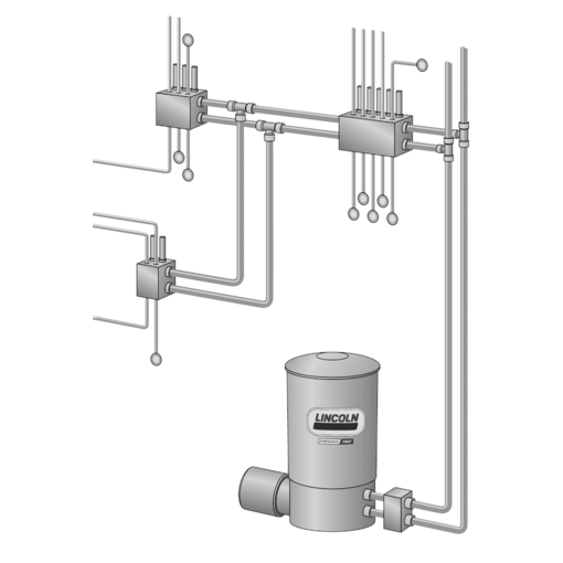
The source of pressure lubricant is the high-pressure piston pump (a). The main distribution of lubricant is made from two branches A and B. The main distribution is connected to the pump through the branch shifting device (b). The dual-line dosing devices (c) are parallel connected to the main distribution. The lubricated places are directly connected to the outlet from the dual-line dosing devices, eventually through the thrusted progressive divider (d) for places with small consumption of lubricant. The system can be equipped by metallicpressure switch (as a part of accessories), which can be used as a control of the shifting device or to check the system functions._x000D_
Function:
The lubrication cycle starts after the break time (of the lubricating interval). It consists of two half-cycles. At the beginning of the half-cycle is the branch A connected with lubricant displacement, the branch B leads back to the tank with lubricant. The rising pressure in the branch A progressively adjusts the pistons of the dosing devices from one position to another. By piston movement is the lubricant forced to appropriate lubricated place. After the repositioning of all pitons of all dosing devices (after the dosing of lubricant in the half ot number of connected lubricated places), the pressure in branch A will rapidly rise. After the switching pressure achievement, the direction of flow in shifting device will be switched, so the branch B is connected with the displacement and the branch A with the tank. So ends the first half cycle. The switching pressure must be set to make the reliable repositioning of all pistons. If the automatic shifting branch device DU1 is used, the switching pressure is set on the shifting device and the branches are switched automatically by pressure of the lubricant. If the electromotive, electromagnetic or pneumatic operated shift device is used, the pressure switch will be placed in front of the furthest dosing device and the impulse for re-construction of the shift device is interfered from that device. The second half-cycle – that means the lubrication of second half of lubricated places, runs the similar way. After one half-cycle ending the pump is generally switched off and the lubricating interval runs again, that means, that every lubricated places obtains the lubricant once after two half-cycles, that means after two lubricating intervals. If the two 3/2 – way valves are used as the shift device, it is useful to proceed both half-cycles subsequently without switching off the pump as a one cycle, because the valves are mono-stable and each half-cycle begins from the same starting position (switch off). It is necessary to register always the last performed half-cycle (branch A or B) in the control system.
By sizing the dual-line system it is necessary to always remember, that the system must be filled by many times more volume of the lubricant than the sum of individual lubricating doses by each lubricating cycle , because some lubricant is used for necessary pressure expansion of distribution and some lubricant is used for shifting the control pistons of dosing devices. This lubricant surplus is returned back into a tank after each cycle. For large lubricating systems it is possible to tree the main distribution by need and individual branches can be separated by electromagnetic locking valves.
In this case it is possible to select different regimes of lubrication for different parts of the machine, eventually to shut down some part due to technological need.
Standard elements for dual-line systems:
a - Pumps
- manual - HJ2
- electric - ZPU 01/02, ZPU 08/14/24, ZPU 75
- pneumatic barrel - Lubrigun, PowerMaster III
- hydraulic barrel - FlowMaster
Each of mentioned group of pumps has its own specific usage. Pneumatic barrel pumps are very useful for very large systems, because other pumps have smaller tanks and it is necessary to refill the lubricant often. By usage of the barrel pumps directly placed into a barrel with lubricant, the risk of lubricant contamination by lubricant refilling is well eliminated.
b – branch shifting device
- automatic, controlled by pressure - D7-G, DU1-G, DU1-GKS
- electric controlled - EM-U2
- electromagnetic controlled - MA, electromagnetic valve 3/2 (2 pcs)
- pneumatic controlled - PM1
- hydraulic controlled - MHY
c – dual-line dosing devices
All above mentioned types of dosing devices are designed with constant volume of lubricant or with infinitely variable dose of lubricant – always for one pair of outlet of the divider. It is possible to equip the dosing devices by electric switches for checking the right function – one switch can monitor only one pair of divider outlets – two lubricated places.
d – progressive dividers
Additional parts of the system:
- Accessories (signalization of low level of the lubricant in the tank, safety valves, manometers, pressure switches, electromagnetic lock valves etc.)
- Lubricant distribution (pipe, hose, screw-coupling, anchoring and assembly material)
Main fields of usage:
Designed for very large devices with long distances between lubricated places, hardworking conditions, e. g. technological devices of cement works, devices for mining and minerals processing – mining giant machines in strip mines, for building materials production, for metallurgical plants – rolling plants, continuous casting, separating lines etc.